Dellorto Motorcycle Carburetor Tuning Guide

  ducatimeccanica.com - home
3.2 Fuel system

First of all, ensure that, with the engine running, fuel flows continuously from the tank to the Carburetor as vibrations from the engine or from the road surface could reduce fuel flow.


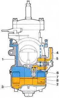
fig.9


It is therefore advisable to use fuel taps and pipes of adequately large size.
Further, check that fuel filter (5) in the union banjo (4) of the Carburetor is clean. Fuel from the tank supplies the Carburetor (fig.9) through a valve in which a float-controlled needle operates (2).

The inlet valve has a brass valve seat inserted (6) where the needle-valve (7) regulates the entry of fuel, pushed upwards by the float by means of the float fork (8) until fuel has reached the specified level.
During engine operation, this provides a constant fuel level in the float chamber so that the distance fuel has to rise to reach the venturi from the various circuits is also constant.

It is important that this level is always constant throughout the operating range because, with a constant depression in the venturi,a rise in the float chamber level would cause an increase in fuel delivery and consequently enrich the mixture; conversely, lowering of the float level causes a weakening of the mixture.

Fuel in the float chamber (3) is always at atmospheric pressure because of the vent holes (1).


3.2.1 Selection of the needle valve size

For a motorcycle with gravity feed from a fuel tank, the fuel inlet valve size, stamped on the seat of the needle-valve itself, should always be 30 % greater than the main jet size.

In case of malfunctioning, you may find that the needle valve size is too small when running the engine at full throttle for a long stretch and that the engine rpm falls, due to the progressive weakening of the carburation.

Conversely, you may get repeated flooding in use where the needle valve seat size is too large.


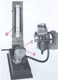
fig.10

On a motorcycle where fuel is supplied to the Carburetor via a fuel pump, a needle valve of smaller size than the main jet is required because the boost pressure is much greater than the pressure head obtainable with the gravity tank.
To avoid the troubles which could be caused by excessive pressure produced by the pump ie. from flooding, it is possible to fit a two-way union to the Carburetor thus permitting excess fuel to return to the tank.
However, it is advisable then to insert a restrictor in the return pipe which reduces the return flow, assuring an adequate supply of fuel to the Carburetor still.
Different types of needle valve are available: metal or viton-rubber-tipped, rigid or spring-loaded needle valve for different applications.
For Carburetor s for motocross, trials, etc, or for engines subject to strong vibrations, spring- loaded valves are required. Needle valve assemblies are supplied individually packed and tested, so it is not advisable to interchange needles and seats with other different sizes and types.

Check the needle valves for leakage with a vacuum gauge (fig. 10), consisting of an air pump A and a mercury manometer B.
Connect the vacuum gauge pipe and the fuel union firmly and hold the Carburetor in the position shown In the picture.


After having primed the air pump of the vacuum gauge by means of the cam C, you will see the mercury in the column rising due to the action of air compressed by the pump; if the mercury column tends to go down, check the complete fuel circuit for leakage; if the fuel circuit is in good working order, the pressure leakage is due to the needle-valve and therefore check it for wear or obstruction and, if necessary, replace it with a complete new assembly of the appropriate size and type.


3.2.2 Selection of the float

The floats currently used are: dual floats connected together (fig 11) and floats with separate parts (fig 12)

In the first type, the floats operate together, while in the second type they can move independently along two guides in the float chamber.


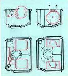
fig. 11 (left)
fig. 12 (right)

This latter type is particularly suitable for Carburetor s on racing motorcycles because it maintains a constant level even in the most arduous conditions of use.

Both types are usually available with two different weights:

a light float to obtain a low level (for two-stroke engines)

a heavy float to produce a higher level (for four stroke engines)

For all floats connected together and floats with independent parts, check the weight marked on them is correct and check that the first type is free to rotate on its pivot pin and is undamaged and that the second ones move freely along their guides and that the separate float arm is undamaged and is free to rotate on its pivot pin.


Check the correct float level position as follows:

for connected floats, hold the Carburetor body in the position shown in fig. 13 and check that the float is at the correct distance from the Carburetor body face as specified in the table.

for the floats with independent parts, hold the Carburetor upside down (fig. 14) and check that the float arm is parallel to the Carburetor face.

Whenever the float or float-arm position does not correspond to the proper specified level setting or is not parallel to the float chamber face, bend the float arms carefully to set the correct position.
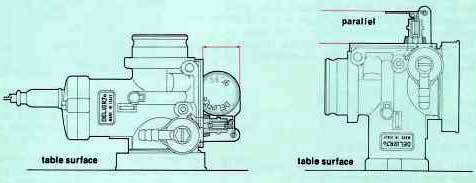
Carburetor
float position mm
PHBG 16.5 + 15.5
PHBL 24.5 + 23.5
PHBH 24.5 + 23.5
PHBE 18.5 + 17.5
PHF 18.5 + 17.5
PHM 18.5 + 17.5


fig. 13
fig. 14

B A C K
I N D E X
N E X T