3.6 Full-throttle operation
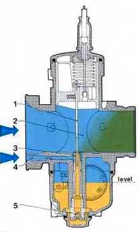
fig. 21
Following the progression phase, on further opening of the throttle, the full-throttle circuit begins to operate. By opening the throttle valve beyond progression, a partial vacuum is created in the mixture chamber, due to the speed of the air being drawn through to the engine, and this vacuum is sufficient to cause fuel to be sucked out of the atomiser nozzle.
In this situation (figure 21), fuel metered by the main jet (5) and further regulated by the atomiser outlet (3) (the atomiser outlet area varies according to the position of the tapered-needle moving up and down through it) is mixed with air from channel (4) and air from the main barrel (2).
The amount of fuel which comes out in the first quarter of the throttle slide movement is determined by the throttle slide cutaway, by the size of the atomiser and by the diameter of the cylindrical part of the tapered-needle at the opening.
From here up to three-quarter throttle, it is deter mined by the atomiser-needlejet size and by the diameter of the tapered-needle at the opening.
From three-quarter throttle to full throttle the amount of fuel depends solely on the size of the main jet.
Therefore you should change the following parts to vary the full throttle circuit delivery:
There are two different full-throttle systems; one is used on two-stroke engines and the other on four-strokes, although some special applications do not conform to this.
3.6.1 Full-throttle system usually used on two-stroke engines
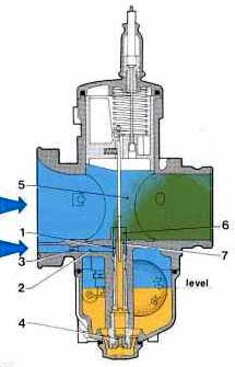
fig. 22
Figure 22 shows the full-throttle mechanism used on two-stroke engines which features an extended nozzle (6) at the end of the atomiser (7); this produces better performance during acceleration.
Air from the inlet (3) passes through channel (2) and flows into the round extension (1) formed by the upper outer end of the atomiser and by the inner part of the nozzle (6). It then mixes with fuel metered through the main jet (4) and coming from the atomiser (7) and then flows into the venturi (5).
A larger atomiser-needlejet size produces an in crease in fuel delivery at all throttle positions and, conversely, a smaller size will produce a decrease in fuel delivery at all throttle openings.
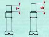
fig. 23
Usually the atomisers on Carburetor s intended for two-stroke engines are manufactured in two types: with either long or short upper parts (figure 23).
The atomisers with longer upper parts cause a weakening of the mixture at low speeds and du ring acceleration from low speed; on the other hand, atomisers with shorter upper parts produce extra enrichment. Carburetor s for racing motor cycles use atomisers with short upper parts.
3.6.2. Full-Throttle system as usually used on 4-Stroke engines (also on 2-Stroke engines in special applications)
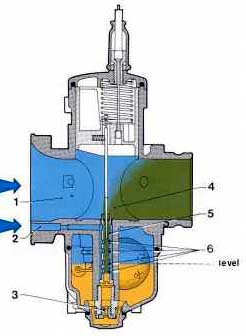
fig. 24
Figure 24 shows the full-throttle system used on four-stroke engines which utilises air to change the amount of fuel delivered by atomiser following sudden throttle openings.
There are several side holes (6) in the atomiser (5), communicating with the air intake (2). On opening the throttle fuel metered by the main jet (3) flows into the atomiser where it mixes with air drawn through the side holes of the atomiser and the resulting fuel-air emulsion flows into the barrel (4) where it further mixes with air coming from the main intake (1).
A larger internal diameter of the needlejet atomiser produces an increase in fuel delivery at all throttle valve positions while a smaller size results in a decrease in fuel delivery at all throttle valve openings.
The atomisers fitted to Carburetor s intended for four-stroke engines are manufactured with different types of side drillings because the positions of these holes affect acceleration response.
Atomiser holes positioned high up cause a weakening in the mixture since they are above the float chamber fuel level and only let air in; conversely, holes lower down cause mixture enrichment because they are below the chamber fuel level and draw fuel from the well to the barrel.
The result is that, to weaken the mixture under acceleration, atomisers with holes drilled higher up are required, while to enrich the mixture, atomisers with holes lower down are needed. The holes' diameter determines how long the well takes to empty and it is therefore also necessary to select a suitable size.
3.6.3. Selection of the throttle valve cutaway.
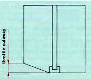 fig. 25
Following progression and on opening the throttle further up to approximately one-quarter, the partial vacuum present in the mixture chamber draws fuel up through the atomiser. In this operating phase the effective fuel passage area is determined by the atomiser-needlejet internal diameter and by the varying section of the tapered-needle moving up and down inside it. The deciding factor which regulates the air flow in this phase is the throttle valve cutaway (figure 25).
A small cutaway creates a greater vacuum and consequently causes a larger amount of fuel to be drawn up through the atomiser ; on the other hand, a larger cutaway would lower the vacuum and therefore reduce the fuel delivered.
Because of this, fitting a lower slide cutaway results in enrichment and vice versa.
3.6.4 - Selection of the tapered needle
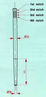 fig.26
The determining features of the tapered needles are:
the diameter A of the cylindrical part
the length C of the tapered part
the diameter B of the tip (figure 26)
You should select the tapered needle considering the elements above in the complete operating range.
The cylindrical part of the needle affects the mixture strength in the first throttle valve movement, up to about a quarter throttle; therefore, in this operating phase, a reduction in the diameter of this cylindrical part produces a mixture enrichment and vice versa.
The tapered part of the needle affects the operating period between a quarter and three-quarter throttle; therefore, for any given tapered part length and cylindrical part diameter, increasing the tip diameter results in the mixture weakening and vice versa.
With the diameter of the tips and the cylindrical parts the same, an increase in the tapered part's length results in an advance of the enrichment of the mixture. By changing the notch positions, therefore, it is possible to raise or to lower the needle
in order to obtain mixture enrichment or mixture weakening over the range regulated by the needle taper.
When major changes in the mixture strength are necessary, change the needle according to the elements and features mentioned above.
In most cases the tapered needle is always held pressed against the atomiser-needlejet's upper edge by a spring located in the throttle slide.
In this way, the position of the needle and the atomiser, and consequently also the fuel delivery, are maintained constant, and thus avoiding excessive wear both of the needle and the needlejet due to vibration.
3.6.5 Selection of the correct size of main jet
The correct main jet size should be selected by running on the road, preferably by first starting with an over-large size jet and gradually reducing it.
At full throttle, turn the starting device (choke) on, thus further enriching the mixture and, if this produces a worsening in engine running ie. it reduces engine rpm, it is advisable to reduce the main jet size until you finally get satisfactory operation.
Other signs revealing the main jet is too big are a very dark exhaust pipe, dark exhaust gases and damp spark plugs and an improvement in engine running when the fuel supply is temporarily shut off.
In a case where too small a main jet has been fitted at first, and the running with the choke on makes a noticeable improvement, you should increase the main jet size until the conditions mentioned above occur.
In selecting the correct main jet, the engine running temperature should be taken into consideration, quite apart from increases in power and top speed, because lean mixtures cause higher running temperatures.
In a situation where a very large increase in the main jet size is required, remember that the main jet flow cross-sectional area should not exceed the effective area for fuel flow between the needlejet and the tapered-needle tip.
Check this with the following formula:
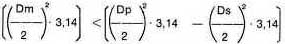
where
Dm is the main jet size
Dp is the atomiser-needlejet size
Ds is the tapered needle tip diameter
All measured in hundredths of a millimeter
For example: main jet 180
needlejet 264
tapered needle tip 170:
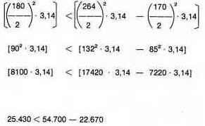
giving the result 25.430 < 32.030 ie. the needle - needlejet clearance is adequate here.